How to make future design provisions for solar installations: a case study for architects
By Duncan Stegmann – Electrical Engineer.
Like many technological developments, solar photovoltaic (PV) technology has matured a lot over the years and is now more affordable and accessible than ever. As a result, supply authorities are increasingly seeking to prolong the life span of existing electrical infrastructure by encouraging excess generation back into the grid.
And yet despite this progress, the installation of solar is still often an afterthought in the project planning process, pursued by owners only during the detailed design phase when floor layouts require drastic change to accommodate solar systems, rather than during DA & BA approval stages.
Leaving it this late in the planning process presents a number of challenges.
The challenge of installing solar on existing property
Installing solar PV to an existing property can prove difficult if there’s no space to locate solar PV inverters and associated equipment. This results in two specific design challenges:
- When there’s limited to no space, the inverters are often installed in any available room or space, sometimes with no ventilation. Inverters typically output enough heat in a small room to warrant concerns of overheating of equipment, thereby reducing their efficiency. To prevent this, rooms without sufficient ventilation require air conditioning.
- Space and heat limitations mean inverters may be installed externally. Since they need to be kept out of direct sunlight, this can mean they require a canopy for shelter, which detracts from the aesthetics of the building and increases the costs of cables between inverters and solar panels and inverters and distribution boards that they may feed into.
So it pays (both financially and aesthetically) for architects and developers to keep future solar installations in mind as early as possible in the design process. When making future provisions for solar installations, there are three key design elements that need to be taken into consideration:
- size and weight of panels
- orientation and layout
- inverters & electrical requirements
Three key design considerations
1. Size and weight of panels
First, it’s critical to allow for the correct size and weight of panels that might be installed. Not allowing sufficient space may result in a less than ideal placement of solar panels or being just a little short from being able to add in another row of panels. A roof structure must be designed to support the additional weight. A poorly designed structure may result in catastrophic failure.
As a guide, the typical size and weight for a commercial solar panel is either:
- 1700mm x 1000mm for a 275W panel and of weight between 18kg and 19kg.
- 2000mm x 1000mm for a 335W panel and weight between 22kg and 23kg.

Figure 1: 335W CanadianSolar KuMax Panel

Figure 2: 275W CSUN Panel
The difference between panel weight will not influence roof support structure design as much as panel size. Using the above dimensions you should lay the panels out and calculate the total power and see which size panel would be optimal for your roof. I explain this in more detail below.
Keep in mind that installers generally require anchor points or edge protection along the roof for safe installation, which means that you will need to include either detail in your architectural drawings.
2. Orientation and layout
The second allowance that needs to be made in the design phase is for the orientation and layout of the panels.
As a general guideline, PV panel generation output is maximised for roof slopes of no more than 30 degrees – in Queensland. For roofs sloping more than 30 degrees, roofs should be orientated North to make most use of the sun as it rises in the East and sets in the West. Minimum slope of roofs/panels should be 10 degrees to facilitate water run-off and self-clean. The further South you are located the more the tilt should be. For example, an ideal tilt in Brisbane is 27 degrees and in Melbourne it’s 37 degrees.
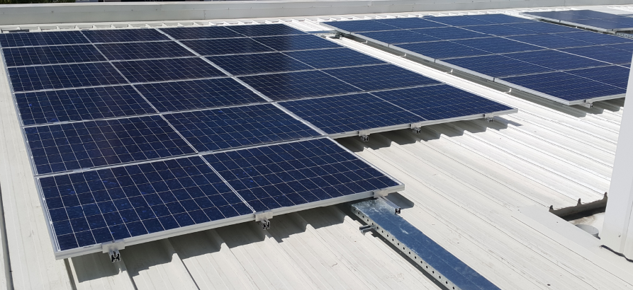
Panels can be installed adjacent to their long sides with two rows back to back on their short sides or installed in rows with a one meter gap between rows for safe maintenance access. There is also a 2m exclusion zone required around the edge of the roof.

Figure 3: The figure above shows 4 rows of panels with 1m spacing between rows.
3. Inverters & Electrical requirements
PV panels aren’t the only equipment you need to be mindful of. A functional system requires several support items such as inverters and protection boxes which all requires sufficient space. These items can also not be easily dealt with by merely throwing them into a room. Where there is power transmitted or generated there is also an efficiency in doing so. Power lost along the way is usually emitted in the form of heat, noise or radiation. So you need to get an idea of how much is emitted by roughly determining the number of inverters that will be needed.
The number of inverters to be installed depends on the number of PV panels and separate orientations of groups of panels. Only PV panels of the same orientation may be connected to any one inverter.
Estimating how many inverters you will need for an installation will require a rough rule of thumb to calculate how many panels you can expect to have on a roof. To estimate the number of panels per row and the number of rows, you can measure the length of the roof and allow for 10% as buffer space. If the roof space will also be used for mechanical or hydraulic equipment then additional allowance should be made for this. Shadowing effects of tall structures should also be considered, but this should be taken into account by the solar design engineer.
To estimate the number of rows, measure the width, divide by 2.5 and round down to the nearest decimal. Now, the total amount of power you expect to generate will depend on the output of the panel. In the case study that follows I have used a 335W panel which is higher than average and slightly more expensive than 270W/275W counterparts.
Below are some illustrations of inverters, protection boxes and cable reticulation.

Figure 4: Typical inverter layout with solar DB and protection box

Figure 5: Typical inverter layout with solar DB and protection box
Other design considerations for the inverters include:
Spatials
Inverters range in output generation from 3kW to 30kW and are dimensioned approximately L800mm x W600mm x D300mm. Multiple inverters will require 300mm clear space on either side and a space for a protection board of size approximately 1200mm x 1200mm. The inverters will only require 600mm clear in front while protection boards will require 600mm clear from an open door. If the protection box has a 600mm door and is 300mm thick, this will require a space that has 1.5m clearance from the wall that the protection box is mounted to.
Location
Inverters should be located as close as possible to PV panel arrays to reduce LV cable lengths and voltage drop. The further away they are from the arrays, the larger the voltage drop at the inverters or the larger the cables will need to be sized to offset this. Submains cabling is then run from the inverters to a local distribution board (DB) or in the first instance to a common electrical board, with multiple circuit breakers, one for each inverter, and then to a local distribution board if there aren’t sufficient spare poles at the DB and/or if the distance between inverters and DB is excessive – more than 50m may be considered excessive.
Some inverters are louder than others, so they should ideally be installed in a suitable location away from where they can be a disturbance.
Inverters should be kept out of direct sunlight due to overheating concerns and will also require ventilation if located within a closed room or cupboard. Inverter output efficiency decreases as temperatures of units rise beyond 40 degrees Celsius, so it is important to keep them cool.
Noise
Some inverters generate more noise than others, with Fronius Symo inverters generating <65dBA and others generating 50dBA. It would be best to consider worst case noise levels when planning an install location for inverters.
Heat
Most inverters have an efficiency rating of 97-98%. This implies that a 30kW inverter would lose up to 2-3% as heat. This suggests that 600W-900W of heat is dissipated at 3.414 BTU/Watt equals 1880-3070 BTU per hour is dissipated. It is clear from this that sufficient ventilation or cooling will be required. This will likely require an AC split system which means you need a condensing unit to be mounted somewhere external to the room.
Risers
Inverters will require a riser or cable pathway to the nearest distribution board.
The protection box will also require a communications pathway between the protection box, other master inverters and the main switchboard where the current transformers will need to be installed. In many cases where PV has been installed at existing sites, wireless transmitters/receivers have been utilised removing the need for communications pathways. However, this approach may introduce reliability concerns with Wifi signal issues.
A warehouse case study
So how might the above work in practice?
The example below shows two warehouses that would be ideal candidates for a solar PV installation. Using the above spatial guidelines, we can estimate an indicative maximum generation output as well as the space requirements for the inverters and associated electrical equipment.

Figure 6: Measurements and Calculations
Firstly, since there are two separate buildings with a physical separation, we will require at least two separate locations for inverters. Given the layout of the larger building, it would be best to split the inverters up into two groups located on the North and South sides of the larger building and on the South side of the smaller building.
As a guideline, inverter groups should be split up if solar panel row lengths exceed 50m. From the calculations in the above image, 10 inverters are required in total, and each group of five inverters will require an approximate width of 510*x+300(x+1). So five inverters will require 510*5+300*6 = 4.35m. Including the protection board (1200 + 300 = 1500mm) gives 5.85m. One protection board will be required for one site as this is the brain that controls the entire solar installation and should be located as close as possible to the site main switchboard. Inverter banks split off from the protection board will require a 600mm wide communications box.
In the case where these inverters are to be installed within a room, an 8kW air conditioner will be required to combat the heat loads generated by the inverters. This implies that a condensing unit will need to be externally located relatively close-by.
What incentives are available?
In my next post, I will analyse the above example from a financial perspective, providing some insight into the various incentives currently available that make solar PV a more attractive investment.
Make sure you’re following the DMA Engineers LinkedIn page to be alerted when it’s posted, or email me at Duncan.stegmann@dmaengineers.com.au and I will send it to you.
If you’d like to join the conversation about this topic, head over to the post on LinkedIn.


SIGN UP TO OUR MAILING LIST
Sign up to receive regular insights on how to create inner beauty in building services, news from DMA and invitations to upcoming events.